Why do I need an active uplink to use an appliance port?

Reader Peter sent the following question as a comment to my Direct Attach Appliance Ports post.

When I connected my NAS to use the appliance port, in order for the vnic of the blade server to communicate with the NAS, i found that there should be a connected uplink port in the 6100 even though I created a private VLAN for the appliance port and the vnic. Why?

I thought the topic would make for a nice brief post explaining the Network Control policy and its effect on Service Profile vNIC objects.

By default, all vNIC configurations use a Network Control Policy called “default” which is created automatically by UCS Manager.

The policy specifies that CDP frames are not delivered to any vNIC using this policy, and that if no uplinks are available, that the vNIC should be brought down.

In Peter’s case, since there were no uplinks available, his vNIC is kept down keeping him from using the appliance connected to the Fabric Interconnect.

If we change the policy to instead to Warning, the vNIC will be kept up (though a system warning will be generated) even when there are no available uplinks.   Note that this effectively disables the Fabric Failover feature on any vNIC using this policy.

If you have some interfaces that you want to stay up even when there are no available uplinks, create a policy with this setting and then specify it in the vNIC configuration.  Alternatively, if you want the default behavior of all vNICs (unless specifically configured) to be that they stay up even when no uplinks are available, you can modify the “default” policy as shown here.

UCSM 1.4 : Maintenance Policies and Schedules

Strange as it may seem with all of the great new features in UCSM 1.4, this is one of my favorites.

To understand the impact, first look at the way disruptive changes were handled prior to this release.   When changing a configuration setting on a service profile, updating service profile template, or many policies, if the change would cause a disruption to running service profiles (i.e. requiring a reboot), you had two options : yes, or no.  When modifying a single profile, this wasn’t a big issue.  You could simply change the configuration when you were also ready to accommodate a reboot of that particular profile.   Where it became troublesome was when you wanted to modify an updating service profile or policy that affected many service profiles – your choice was really only to reboot them all simultaneously, or modify each individually.   Obviously for large deployments using templates and policies (the real strength of UCS), this wasn’t ideal.

With UCSM 1.4, we now have the concept of a Maintenance Policy.   The screenshot below is taken from the Servers tab:

Creating a Maintenance Policy allows the administrator to define the manner in which a service profile (or template) should behave when disruptive changes are applied.   First, there’s the old way:

A policy of “Immediate” means that when a disruptive change is made, the affected service profiles are immediately rebooted without confirmation.   A normal “soft” reboot occurs, whereby a standard ACPI power-button press is sent to the physical compute node – assuming that the operating system traps for this, the OS should gracefully shut down and the node will reboot.

A much safer option is to use the “user-ack” policy option:

When this option is selected, disruptive changes are staged to each affected service profile, but the profile is not immediately rebooted.   Instead, each profile will show the pending changes in its status field, and will wait for the administrator to manually acknowledge the changes when it is acceptable to reboot the node.

The most interesting new option is the is the “timer-automatic” setting.   This setting allows the maintenance policy to reference another new object, the Schedule.

Schedules allow you to define one-time or reoccurring time periods where one or more of the affected nodes may be rebooted without administrator intervention.  Note that the Schedules top-level object is located within the Servers tab:

The only schedule created automatically by UCSM is the “default” schedule, which has one recurring entry to reboot all service profiles that reference a “timed-automatic” maintenance policy associated with the “default” schedule each day at midnight.   This “default” schedule can be modified, of course.

Creating a user-defined schedule provides the ability to control when – and how many – profiles are rebooted to apply disruptive changes.

The One Time Occurrence option sets a single date and time when this schedule will be in effect.  For example, if you wanted all affected profiles to be rebooted on January 18th at midnight, you could create an entry such as the following.

Once the date and time have been selected, the other options for the occurrence can be selected.

Max Duration specifies how long this occurrence can run.   Based on the other options selected below it, it is possible that all service profiles may not be able to be rebooted in the time allotted.   If this is the case, changes to those profiles will not take effect.

Max Number Of Tasks specifies how many total profiles could be rebooted by this occurrence.

Max Number Of Concurrent Tasks controls how many profiles can be rebooted simultaneously.   If, for example, this schedule will be used on a large cluster of service profiles where workload can be sustained even while 5 nodes are unavailable, set this value to 5 and the reboots will occur in groups of that size.

Minimum Internal Between Tasks allows you to set a delay between each reboot.  This can be set to ensure that each node rebooted is given time to fully boot before the next node is taken down.

The Recurring Occurrence option provides for the creation of a schedule that will run every day, or on a specific day, to apply disruptive changes.

This option has the same per-task options as the previous example.

Once you have created your maintenance policy and schedule (if necessary), the service profile or service profile template must reference the maintenance policy in order for it to have any effect.  After selecting your service profile or template, the Actions window has an option to Change Maintenance Policy.

You may then select the Maintenance Policy you wish to use, or create a new one.

The service profile properties will now show that a maintenance policy has been selected.

In this example, a policy requiring user acknowledgement has been chosen.   Now if any disruptive changes are made, the service profile will not reset until manually acknowledged by an administrator.   Any time profiles are awaiting acknowledgement, a warning “Pending Activities” will be shown on the UCSM status bar.

Within the profile properties, a description of the pending changes will be displayed along with the “Reboot Now” option.

I hope this description of the new maintenance policies and schedules options was helpful.  I’m very excited by all the new features rolling into UCS – it was a great system before, and it’s only getting better!

UCSM 1.4 : Where to find firmware now

Prior to UCSM 1.4, all UCS firmware was delivered as a single bundle – this included UCSM itself, the code for the Fabric Interconnects, IO Modules, blades, mezzanine cards, etc.   With UCSM 1.4, code is now delivered in three different packages.   This makes it easier for Cisco to release support for new blades, mezzanine cards, etc, without having to release a new version of UCSM.

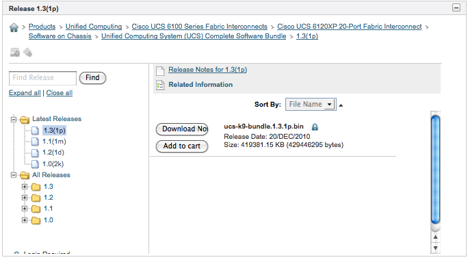
First, the old way:

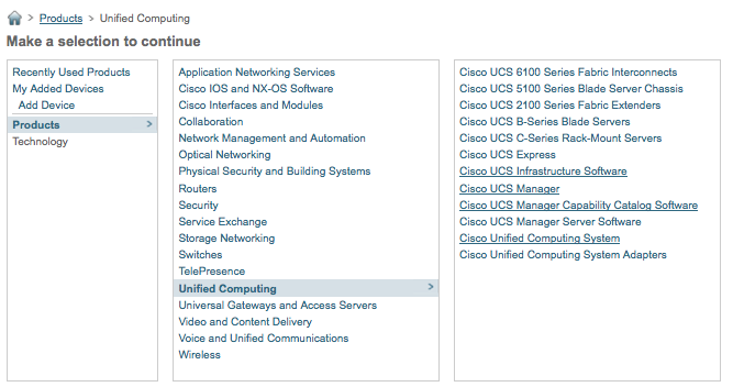
Note the path to the software – you’d navigate to the Fabric Interconnect and select “Complete Software Bundle”.   As of December 31, 2010, the last version posted her is 1.3(1p) – even though 1.4 has been released.   This is due to the new way code is distributed.   Instead of going to a specific piece of hardware, navigate to Products/Unified Computing and review the options listed:

The three new categories are “Cisco UCS Infrastructure Software”, “Cisco UCS Manager Server Software”, and “Cisco UCS Manager Capability Catalog Software”.

The “Infrastructure Software” category contains UCSM, and the firmware/software for the Fabric Interconnects, IO Modules, and FEX modules (for C-series attachment).

“Cisco UCS Manager Server Software” has two sub-categories, one for B-series blades and one for C-series rack-mount servers.

Finally, the “UCS Manager Capability Catalog Software” category contains a small file that describes (to UCSM) all of the components of a UCS system for inventory, categorization, etc.   If Cisco were to release, say, new fan modules that had different specifications than the existing ones, only this file would need to be updated instead of a full system-wide upgrade.

I hope this helps when going looking for the latest code for your UCS system!

UCSM 1.4 : Direct upload of firmware bundles

Ok, so this one isn’t earth-shattering, but I thought it was worth mentioning.

Previous to UCSM 1.4, the only way to transfer bundles of firmware to UCSM was via an external server – FTP, TFTP, SCP, or SFTP.   In most shops, this isn’t a big deal – you likely already have a utility server of some type available on your management network(s) for other similar tasks.   In some scenarios (especially greenfield deployments), though, you may not have ready access to such a server or for other reasons may not want to put your UCS code there.

With 1.4, you can now upload firmware directly from the UCSM client.   When selecting the Download Firmware option in Firmware Management,

You are now presented with the option to either upload a file from your local workstation,

or use the traditional method transferring the file from a remote server.

Again, not a huge deal, but definitely a nice convenience enhancement.

UCSM 1.4 : Direct attach appliance/storage ports!

One of the most often requested features in the early days of UCS was the ability to directly attach 10GE storage devices (both Ethernet and FCoE based) to the UCS Fabric Interconnects.

Up until UCSM 1.4, only two types of Ethernet port configurations existed in UCS – Server Ports (those connected to IO Modules in the chassis) and Uplink Ports (those connected to the upstream Ethernet switches).   As UCS treated all Uplink ports equally, you could not in a supported manner connect an end device such as a storage array or server to those ports.   There were, of course, clever customers who found ways to do it – but it wasn’t the “right” or most optimal way to do it.

Especially within the SMB market, many customers may not have existing 10G Ethernet infrastructures outside of UCS, or FC switches to connect storage to.   For these customers, UCS could often provide a “data center in a box”, with the exception of storage connectivity.   For Ethernet-based storage, all storage arrays had to be connected to some external Ethernet switch, while FC arrays had to be connected to a FC switch.   Adding a 10G Ethernet or FC switch just for a few ports didn’t make a lot of financial sense, especially if those customers didn’t have any additional need for those devices beyond UCS.

With UCSM 1.4, all of that changes.   Of course, the previous method of connecting to upstream Ethernet and FC switches still exists, and will still be the proper topology for many customers.  Now, however, a new set of options has been opened.

Take a look at some of the new port types available in UCSM 1.4 :

New in 1.4 are the Appliance, FCoE Storage, Monitoring Ethernet, Monitoring FC, and Storage FC port types.

I’ll cover the Monitoring types in a later post.

On the Ethernet side of things, the Appliance and FCoE Storage allow for the direct connection of Ethernet storage devices to the Fabric Interconnects.

The Appliance port is intended for connecting Ethernet-based storage arrays (such as those serving iSCSI or NFS services) directly to the Fabric Interconnect.   If you recall from previous posts, in the default deployment mode (Ethernet Host Virtualizer), UCS selected one Uplink port to accept all broadcast and multicast traffic from the upstream switches.   By adding this Appliance port type, you can ensure that any port configured as an Appliance Port will not be selected to receive broadcast/multicast traffic from the Ethernet fabric, as well as providing the ability to configure VLAN support on the port independently of the other Uplink ports.

The FCoE Storage Port type provides similar functionality as the Appliance Port type, while extending FCoE protocol support beyond the Fabric Interconnect.   Note that this is not intended for an FCoE connection to another FCF (FCoE Forwarder) such as a Nexus 5000.   Only direct connection of FCoE storage devices (such as those produced by NetApp and EMC) are supported.   When an Ethernet port is configured as an FCoE Storage Port, traffic is expected to arrive without a VLAN tag.   The Ethernet headers will be stripped away and a VSAN tag will be added to the FC frame.   Much as the previous FC port configuration was, only one VSAN is supported per FCoE Storage Port.   Think of these ports like an Ethernet “access” port – the traffic is expected to arrive un-tagged, and the switching device (in this case, the Fabric Interconnect) will tag the frames with a VSAN to keep track of it internally.   When the frames are eventually delivered to the destination (typically the CNA on the blade), the VSAN tag will be removed before delivery.   Again, it’s very similar to traffic flowing through a traditional Ethernet switch, access port to access port.   Even though both the sending and receiving devices are expecting un-tagged traffic, it’s still tagged internally within the switch while in transit.

The Storage FC Port type allows for the direct attachment of a FC storage device to one of the native FC ports on the Fabric Interconnect expansion modules.  Like the FCoE Storage Port type, the FC frames arriving on these ports are expected to be un-tagged – so no connection to an MDS FC switch, etc.   Each Storage FC Port is assigned a VSAN number to keep the traffic separated within the UCS Unified Fabric.   When used in this way, the Fabric Interconnect is not providing any FC zoning configuration capabilities – all devices within a particular VSAN will be allowed, at least at the FC switching layer (FC2), to communicate with each other.   The expectation is that the devices themselves, through techniques such as LUN Masking, etc, will provide the access control.   This is acceptable for small implementations, but does not scale well for larger or more enterprise-like configurations.   In those situations, an external FC switch should be used either for connectivity or to provide zoning information – the so-called “hybrid model”.   I’ll cover the hybrid model in a later post.

What’s cool in UCSM 1.4?

Since so many other great bloggers announced earlier this month that Cisco had released UCS Manager 1.4 (codenamed ‘Balboa’), I didn’t see any reason to wade into the fray with yet another summary of the release notes.   For one such excellent summary, see Steve Chamber’s post here: http://viewyonder.com/2010/12/20/ciscoucs-1-4-is-here/

Instead I thought it might be useful, especially for those new to UCS, to do a series of posts on the new features (there’s a ton of them!) and what they really mean to an existing or potential UCS shop.   I’m really excited by this release, as there are so many cool new things that really cement UCS as a top-notch architecture.  So many of my wish-list items have been fulfilled by this release.  Many of the features I’ve heard customers asking for have been delivered in 1.4, so I’m sure this upgrade is going to make a lot of people very happy.

So, I have a handful of features that I plan to detail over the next few days and weeks, but I’d like to know – what features are you most curious about?  What features perhaps do you not see the value of?   Your comments will help me prioritize my posts!

Why doesn’t Cisco…?

I get asked a lot why Cisco doesn’t have feature X, or support hardware Y in their UCS product line.   A recent discussion with a coworker reminded me that lots of those questions are out there, so I might as well give my opinion on them.

Disclaimer : I don’t work for Cisco, I don’t speak for Cisco, these are just my random musings about the various questions I hear.

Why doesn’t Cisco have non-Intel blades, like AMD or RISC-type architectures?  Are they going to in the future?

As of today, Intel processors (the Xeon 5500/5600, 6500/7500 families) represent the core (pun intended) of the x86 processor market.  Sure, even Intel has other lines (Atom, for one), and AMD still makes competitive processors, but most benchmarks and analysts (except for those employed by other vendors) agree that Intel is the current king.   AMD has leapfrogged Intel in the past, and may do so again in the future, but for right now – Intel is where it’s at.

If you look at this from a cost-to-engineer perspective, it starts to make sense.   It will cost Cisco just as much to develop an AMD-based blade as it does for the more popular and common Intel processors.   Cisco may be losing business to customers that prefer AMD, but until they’ve run out of customers on the Intel side of things, it just doesn’t make financial sense to attack the AMD space as well.

As for RISC/Unix type architectures (really, any non-x86 platform), who’s chip would they use?  HP?  Not likely.  IBM?  Again, why support a competitor’s architecture – especially one as proprietary as IBM.  (Side note – I’m a really big fan of IBM AIX systems, just not in the “blade” market)   Roll their own?  Why bother?  It’s still a question of return on investment.   Even if Cisco could convince customers to abandon their existing proprietary architectures for a Cisco proprietary processor, how much business do you really think they’d do?   Nowhere near enough to justify the development cost.

Why doesn’t Cisco have Infiniband adapters for their blades?  What about the rack-mount servers?

One of the key concepts in UCS is the unified fabric, using only Ethernet as the chassis-to-Fabric Interconnect topology.  By eliminating protocol-specific cabling (Fibre Channel, Infiniband, etc), the overall complexity of the environment is reduced and the bandwidth is flexibly allocated between upper (above Ethernet) layer protocols.   Instead of having separate cabling and modules for different protocols (a la legacy blade architectures), any protocol needed is encapsulated over Ethernet.   Fibre Channel over Ethernet (FCoE) is the first such implemenatation in UCS, but certainly won’t be the last.

Infiniband as a protocol has a number of compelling features for certain applications, so I’d definitely see Cisco supporting RDMA over Converged Ethernet (RoCE) in the future.  RoCE does for Infiniband what FCoE does for Fibre Channel.  The underlying transport is replaced with Ethernet, while keeping the protocol intact.  Proponents of Infiniband will point to the transport’s legendary latency characteristics, specifically low and predictable.   The UCS unified fabric architecture provides just such an environment – low, predictable latency that’s consistent in both inter- and intra-chassis applications.

As for the rack-mount servers, there’s nothing stopping customers from purchasing and installing their own PCI Infiniband adapters.   Cisco isn’t producing one, and won’t directly support it – but rather treats it as a 3rd party device to be supported by that manufacturer.

What about embedded hypervisors?

Another key feature of UCS is that the blades themselves are stateless, at least in theory.  No identity (MACs, WWNs, UUIDs, etc), no personality (boot order, BIOS configuration) until one is assigned by the management architecture.    Were the blades to have an embedded hypervisor, that statelessness is lost.  Even though it’s potentially a very small amount of stateful data (IP address, etc), it’s still there.   This is probably the most-likely to be supported question in my list.  My expectation is that at some point in the future, the UCS Manager will be able to “push” an embedded hypervisor, along with its configuration, to the blade along with the service profile.   By making UCS Manager the true stateful owner of the configuration data, having a “working copy” on the blade becomes less of an issue.

Final thoughts…

I’ve used this analogy in the past, so I’ll repeat it here.   I look at UCS as sort of the Macintosh of the server world.   It’s a closely controlled set of hardware in order to provide the best possible user experience, at the cost of not supporting some edge-case configurations or feature sets.   No, you can’t have Infiniband, or GPUs on the blade, or embedded hypervisors.   The fact is that the majority of data center workloads don’t need these features.   If you need those features, there are plenty of vendors that provide them.  If you want a single vendor for all your servers – regardless of edge-case requirements – there are certainly vendors that provide that (HP, IBM, etc).   In my opinion, though, it’s that breadth of those product offering that makes those solutions less attractive.   In accommodating for every possible use case, you end up with a very complex architecture.   Cisco UCS is streamlined to provide the best possible experience for the bulk of data center workloads.   Cisco doesn’t need to be, or want to be as near as I can tell, an “everything to everybody” solution.  Pick something you can do really, really well and do it better than anyone else.   Let the “other guys” work on the edge cases.  Yes – that will cost Cisco some business.   Believe it or not, despite what the rhetoric on Twitter would have you believe, there’s enough business out there for all of these server vendors.   Cisco, even if they’re wildly successful in replacing legacy servers with UCS, isn’t going to run HP or IBM or Dell out of business.   They don’t need to.   They can make a lot of money, and make a lot of customers very happy, co-existing in the marketplace with these vendors.   Cisco provides yet another choice.   If it doesn’t meet your needs, don’t buy it.   🙂

No offense or disrespect is intended to my HP and IBM colleagues.   You guys make cool gear too, you’re just solving the problems in a different way.   Which way is “best”?  Well, now, that really comes down to the specific customer doesn’t it?

Chassis Discovery Policies in UCS

Cisco UCS provides a configurable “Chassis Discovery Policy” that affects how chassis links (called “Server Ports”) are activated when discovering a new chassis.  See this page on cisco.com.

After a recent discussion on Twitter, I decided to test out a few scenarios.

My configuration is a pair of UCS 6120 Fabric Interconnects, two UCS 5108 Chassis, with 2 links per IO Module.

Additionally, this particular lab is on a reasonably old version of UCSM code, 1.0(1f).    I’m not in a position to upgrade it at the moment – I can re-test at a later date with more current code.  I don’t expect the behavior to change, however.

I started with the default discovery policy of 1-link.   I enabled one link per fabric interconnect to a chassis, and checked the status of the ports.   The ports were in an “Up” Overall Status, which is proper – and means that the link is available for use.   I then enabled a second link per fabric interconnect to the same chassis.   The second activated link went into a “Link Up” state, with “Additional info” of “FEX not configured”.   This means that the physical link has been activated, but is not in use – the IO Module (FEX) is not using the link.   A re-acknowledgement of the chassis activates the second link.

I then changed the discovery policy to 4-links.   I enabled one link per fabric interconnect to a different chassis, and checked the status of the ports.  The ports went into the “Link Up” state, “FEX Not Configured” – in other words, the links are not use.   While we can detect that the chassis is present, no traffic will flow as the FEX has not yet been configured to pass traffic.   Furthermore, the chassis is an error state, in as much as the cabling doesn’t match the chassis discovery policy.

Reacknowledging the chassis activates the links, and removes the error condition, even without changing the discovery policy.

Finally, I tested the scenario of setting the chassis discovery policy to 2 links and activating only one link per Fabric Interconnect.   As expected, the link enters the “link-up”, “FEX not configured” state.   I then activated a second link per Fabric Interconnect.   After a brief period, both ports per Fabric Interconnect enter the “Up” status.

In short, setting the Chassis Discovery Policy determines how many links must be present per Fabric Interconnect to an IO Module before the ports are activated and the chassis is put into service.   If the policy is set at 1 link, and more than 1 link are activated, a simple re-acknowledgement of the chassis will activate the additional links.   If the policy is set to a higher number – and that number of links are not present – the chassis will not be activated unless a manual re-acknowledgement is done.

Frankly, I don’t see a lot of value in this feature – unless you’re adding a large number of chassis that will all have identical numbers of uplinks.  Even then, you’re saving yourself at most a few clicks of the mouse to re-ack the chassis that don’t match the policy.   Why not simply leave the policy at default and re-ack any chassis that has more than 1 link per IOM?   Presumably you’re going to do this before actually deploying any service profiles, so there’s no potential for disruption with the re-ack.

Thoughts or comments?

UCSM 1.3(1c) Released!

Cisco has released UCS Manager version 1.3(1c).   This is the first public release in the 1.3 line, also known as “Aptos+”.

Release notes are here: http://www.cisco.com/en/US/docs/unified_computing/ucs/release/notes/ucs_22863.html

Haven’t gotten a chance to play with the new version yet, but there are some significant enhancements.    Among them…

  • 1 GE support on UCS6120 and UCS6140 Fabric Interconnects
    • On the 6120, you can now use 1GE transceivers in the first 8 physical ports.
    • On the 6140, you can now use 1GE transceivers in the first 16 physical ports.
    • Watch for a post soon on why I think this is a bad idea.  🙂
  • Support for the new, 2nd generation mezzanine cards
    • Both Emulex and Qlogic have produced a 2nd generation mezzanine card, using a single-chip design which should lower power consumption
      • Be warned that these new mezzanine cards won’t support the “Fabric Failover” feature as supported by the first generation CNAs, or by the VIC (Palo) adapter
      • These aren’t shipping quite yet, but will be soon
    • A Broadcom BCM57711 mezzanine adapter
      • This will compete with the Intel based, 10GE mezzanine adapters that UCS has had until now
      • The Broadcom card supports TOE (TCP Offload Engine) and iSCSI Offload, but not iSCSI boot
    • An updated Intel mezzanine adapter, based on the Niantic chipset
  • Support for the B440-M1 blade
    • The B440 blade will be available in a 2 or 4 processor configuration, using the Intel Xeon 7500 processors
    • Up to 4 SFFP hard drives
    • 32 DIMM slots, for up to 256GB of memory
    • 2 Mezzanine slots
    • Full-width form factor
  • SSD hard drive support in B200-M2, B250-M2, and B440-M1 blades
    • First drive available is a Samsung 100GB SSD
  • Improved SNMP support
  • Ability to configure more BIOS options, such as virtualization options, through the service profiles
    • This is a big step towards making UCS blades honestly and truly stateless
    • Previously, I’d recommended that UCS customers configure each blade’s BIOS options to support virtualization when they received them, whether or not they were going to use ESX/etc on all of the blades.  This way they didn’t have to worry about setting them again when moving service profiles
  • Support for heterogeneous mezzanine adapters in full-width blades
  • Increased the supported limit of chassis to 14.
  • Increased the limit of VLANs in UCSM to 512
    • There’s been some discussion around this lately, particular in the service provider space.   Many service providers need many more VLANs than this for their architectures.
    • I’ve seen reference to a workaround using ESX, Nexus 1000V, private VLANs, and a promiscuous VLAN through the Fabric Interconnect into an upstream switch, but I’m still trying to get my head around that one.  🙂
  • Ability to cap power levels per blade
    • Will have to wait until I get a chance to test out the code level to see what kinds of options are available here

Looking forward to seeing customer reaction to the new features.

UCS with disjointed L2 Domains

How do we deal with disjointed L2 domains in UCS?

To start, what’s a disjointed L2 domain?  This is where you have two Ethernet “clouds” that never connect, but must be accessed by the same UCS Fabric Interconnect.   Take, for example, a multi-tenant scenario where we have multiple customer’s servers within the same UCS cluster that must access different L2 domains.

How do we ensure that all traffic from Customer A’s blade only goes to their cloud, while Customer B’s blades only connect to their cloud?

The immediately obvious answer is to use UCS pin groups to tie each customers interfaces (through their vNIC configuration) to the uplinks that go to their cloud.   Unfortunately, this only solves half of the problem.

In the default operational mode of the Fabric Interconnects (called Ethernet Host Virtualizer, sometimes called End Host Virtualizer), only one uplink is used to receive multicast or broadcast traffic.   EHV mode assumes a single L2 fabric on the uplinks (VLAN considerations notwithstanding).  So in this example, only broadcasts or multicasts from one of the two fabrics would be accepted.   Obviously, this is a problem.

The only way to get around this is to put the Fabric Interconnects into Ethernet Switching mode.   This causes the Fabric Interconnect to behave as a standard L2 switch, including spanning tree considerations.  Now uplinks can receive broadcasts and multicasts regardless of the fabrics they are connected to.   This does, however, increase the administrative overhead of the Fabric Interconnects and reduces your flexibility in uplink configuration since now we must channel all ports going into the same L2 domain in order to use the bandwidth.

To me, a more ideal situation would be to leave the Fabric Interconnects in EHV mode, and use another L2 switch to perform the split between fabrics, such as the following:

This configuration allows the Fabric Interconnect to remain in EHV mode and has the upstream L2 switches performing the split between the L2 domains.  ACLs can be configured on the L2 switches as necessary to isolate the networks, something that cannot be done on the Fabric Interconnect regardless of mode.

Both of these scenarios assume that each of the two customer L2 clouds are using different VLAN numbering, since there’s no capacity in UCS to distinguish between the same VLAN numbers on either Fabric.   There are certainly L3 and other translation tricks that you could use to accomodate this, but that’s an entirely different post.  🙂